
Choosing Fluid-Control Accessories for CO₂RR GDE Flow Cells
Once a GDE flow cell has been selected, the next practical questions are often about the surrounding fluid-control hardware: How should CO₂ feed be controlled? Which pump is appropriate for electrolyte circulation? What should be done when gas accumulates in the liquid loop? And how can liquid-side pressure be adjusted to avoid flooding or gas breakthrough? These choices are not merely plumbing details. Gas delivery, liquid circulation, bubble transport, and pressure balance together define the operating environment at the gas-liquid-solid interface [1,5,7].
Following Blog 3 on flow-cell selection, this article focuses on the surrounding fluid-control hardware. This article is organized as a selection guide rather than a component list. It follows the fluid path from Gas to Pump to Pressure / Water Management and then to Supporting Accessories. Independent literature is used to explain why each control variable matters, while the ANR modules are discussed as practical hardware options for controlling those variables. The cited literature was generated using independent research systems and should not be interpreted as direct performance validation of ANR products.
1. Gas Supply and Flow Control
A GDE shortens the CO₂ mass-transfer pathway by supplying gaseous CO₂ close to the catalyst layer [1,5]. The inlet flow, however, still has to match the active area, operating current, flow-field geometry, and desired CO₂ utilization. Too little gas can lead to downstream reactant depletion, while excessive feed may maintain reactant availability at the cost of lower single-pass utilization.
Subramanian, Middelkoop, and Burdyny demonstrated this trade-off in a CO₂-to-CO membrane-electrode-assembly system operated at 200 mA cm⁻². Changing the inlet CO₂ flow altered both product Faradaic efficiencies and measured CO₂ utilization [2]. Their exact flow values are specific to the 5 cm² MEA, serpentine flow field, and operating conditions used in that study, so they should not be transferred directly to another reactor.
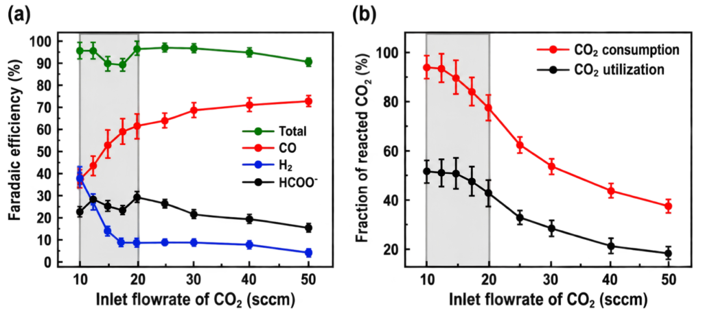
Figure 1. Effect of inlet CO₂ flow rate on product Faradaic efficiency and CO₂ utilization in the authors’ specific CO₂ electrolysis system. Reproduced from Fig. 2a–b of Ref. [2].
Selecting the gas-control module: The current ANR CO₂ Reduction Complete System lists the EC-MFM+EC-MFC Mass Flow Meter & Controller for defined, adjustable, and repeatable gas delivery. The catalogue provides flow ranges of 0-500 SCCM and 0-30 SLM, with a control range of 2-100% of full scale. The appropriate range should be selected from the expected operating flow, not from electrode area alone.
- Use a lower-range configuration when fine control of laboratory-scale CO₂ feed is the main requirement.
- Use a higher-range configuration when the system requires substantially greater total gas throughput or when larger flow capacity is needed.
- For reproducibility, record inlet flow together with active area and current. When CO₂ utilization or carbon balance is important, outlet flow and gas composition should also be considered.
Selection takeaway: Do not use one universal SCCM value for every GDE. Select a controller range that gives stable resolution around the intended operating flow, then establish the actual setpoint for the specific cell and test condition.
2. Pump Selection for Circulation and Bubble Handling
Electrolyte circulation affects residence time, boundary-layer transport, local ion concentration, local pH, soluble-product removal, bubble transport, and the liquid-side pressure experienced by the GDE. Increasing pump speed is therefore not automatically beneficial: insufficient convection can allow gas accumulation, while excessive convection can change the local chemical environment at the catalyst surface [3,8].
Filippi et al. investigated four catholyte-compartment designs with Cu-based GDEs over 50-700 mA cm⁻² and linked local velocity distribution to bubble transport and local pH [3]. Under their specific geometries and conditions, a relatively homogeneous velocity distribution around 0.01-0.1 m s⁻¹ was associated with favorable C₂+ production. The authors proposed a hydrodynamic “volcano” model: bubble removal can become limiting at low local velocity, whereas stronger convection at high local velocity can reduce local pH and favor competing reactions. This range is a study-specific result, not a universal pump specification.
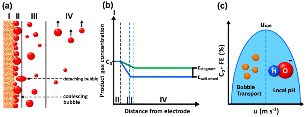
Figure 2. Bubble-transport model and the proposed hydrodynamic relationship between catholyte velocity, bubble removal, local pH, and C₂+ selectivity. Reproduced from Fig. 4d–f of Ref. [3].
The practical pump decision is therefore based on what the liquid loop needs to do. ANR currently lists two different pump types, and their intended functions should not be treated as interchangeable.
Table 1. Practical distinction between the PMP-1 and PMP-2 based on the current ANR product documentation.
|
Selection factor |
PMP-1 Peristaltic Pump |
PMP-2 Gas-Liquid Mixing Pump |
|
Primary need |
Adjustable electrolyte transfer and circulation |
Gas-containing liquid circulation and bubble dispersion |
|
Best fit |
Routine filling, flushing, and circulation where controlled liquid delivery is the main requirement |
Loops where significant gas accumulation occurs, especially in gas-evolving compartments |
|
Catalogue flow specification |
0-35 mL/min; 0-200 rpm |
140-170 mL/min; operating pressure 90 kPa |
|
Fluid-contact hardware |
2 mm ID / 4 mm OD tubing |
Compatible with 3 mm PTFE tubing |
|
Flow-management focus |
Controlled liquid transfer and circulation |
Efficient gas bubble removal and high-shear gas dispersion |
Selection takeaway: Choose PMP-1 when adjustable liquid circulation is the main task. Choose PMP-2 when persistent gas accumulation in the liquid loop is itself the problem to be managed. This is a functional distinction, not a strict catholyte-versus-anolyte rule.
3. Pressure Balance and Water Management
A GDE separates a gas compartment from a liquid electrolyte compartment. The pressure difference across the porous electrode, together with pore structure and wettability, determines whether the intended flow-by regime is maintained or whether one phase breaks through into the other. Liquid overpressure can promote electrolyte flooding into gas-transport pores, while gas overpressure can drive bubbles into the liquid compartment [4,5].
Baumgartner et al. directly examined this behavior using Ag-coated gas-diffusion materials under controlled differential pressure [4]. Their Figure 1 distinguishes gas breakthrough, balanced flow-by operation, and GDE flooding. The important selection lesson is that pressure balance is a controllable operating variable rather than an incidental consequence of tubing and reservoir layout.
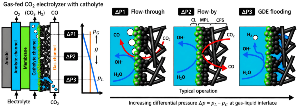
Figure 3. Gas-liquid flow regimes at a GDE as a function of differential pressure, illustrating gas breakthrough, balanced flow-by operation, and electrolyte flooding. Reproduced from Fig. 1 of Ref. [4].
One practical contribution to liquid-side pressure is hydrostatic head. For a static liquid column, the hydrostatic contribution scales with ρgΔh, where Δh is the relevant liquid-height difference. Changing the relative height of the cell or liquid level can therefore change the liquid-side pressure condition even when the pump setting is unchanged.
Selecting the water-management hardware: The ANR EC-WM Water Management System is a height-adjustable platform designed to change the relative position of the GDE flow cell. The current catalogue specifies an effective stroke of 260 mm and a graduated fine-adjustment mechanism. Its intended function is to assist gas-liquid pressure balancing and help avoid flooding or gas breakthrough by modifying the hydrostatic liquid-side condition.
This is different from controlling the entire pressure drop of the loop. Tubing resistance, flow-channel resistance, pump operation, and gas-side pressure may also contribute to the total pressure difference. The EC-WM should therefore be understood as a controlled way to adjust the hydrostatic contribution rather than as a universal back-pressure regulator.
Water management in the broader electrochemical sense also includes local water distribution, membrane hydration, ion transport, and carbonate chemistry. Salt precipitation can become a secondary stability issue when local water and ion transport shift [6], but the relevant mitigation strategy depends strongly on cell architecture. It should therefore not be treated as the primary selection criterion for a catholyte-fed GDE flow-cell accessory.
Selection takeaway: Use EC-WM when the experiment requires controlled adjustment of the cell/liquid-height relationship to tune the hydrostatic liquid-side condition. If direct pressure measurement or active pressure regulation is required, that requirement should be specified separately.
4. Supporting Accessories
The main control modules do not operate in isolation. Reservoirs, a gas buffer, tubing, connectors, and the overall routing of the loop define fluid inventory, pressure losses, dead volume, and the repeatability of the boundary conditions. These components are simple in appearance but should be selected and arranged deliberately.
Table 2. Supporting fluid-path components and the variables they help standardize.
|
Accessory |
Primary role |
Practical selection / setup point |
|
Anolyte / Catholyte Reservoirs |
Electrolyte storage and circulation inventory |
Keep the liquid level and reservoir position reproducible when hydrostatic head can affect the GDE. |
|
Gas Buffer |
Gas-pressure buffering and flow stabilization |
Useful when gas delivery or downstream flow produces fluctuations that should be decoupled from the cell. |
|
PTFE Tubing & Connectors |
Chemically resistant interconnection |
Use chemically compatible tubing and keep inner diameter, length, and routing consistent because these influence flow resistance and holdup. |
For repeatable experiments, the fluid path should be documented as part of the setup rather than treated as an invisible background detail. At minimum, record the tubing type and approximate dimensions, reservoir arrangement, flow direction, and any components inserted between the controller / pump and the cell.
5. Quick Selection Guide
The most useful way to select the accessories is to start from the variable that needs to be controlled. The table below summarizes the selection logic developed in the preceding sections.
Table 3. Accessory selection by experimental control requirement.
|
Experimental need |
Primary module |
Selection logic |
|
Define and reproduce CO₂ feed |
EC-MFM+EC-MFC |
Choose a flow range that provides useful control around the intended operating flow; do not select a fixed SCCM value from electrode area alone. |
|
Adjustable electrolyte circulation |
PMP-1 |
Use when routine liquid delivery, filling, flushing, and circulation are the main tasks. |
|
Persistent gas accumulation in liquid loop |
PMP-2 |
Use when bubble removal / gas dispersion is a primary fluid-management requirement, especially in gas-evolving compartments. |
|
Flooding or gas breakthrough sensitive to liquid height |
EC-WM |
Use cell-height adjustment to tune the hydrostatic contribution to liquid-side pressure. |
|
Stable storage and interconnection |
Reservoirs + Gas Buffer + PTFE Tubing |
Standardize liquid inventory, gas buffering, tubing dimensions, and loop routing. |
Diagnostic tip: If flooding or gas breakthrough persists after EC-WM adjustment, check gas-side pressure, tubing and channel resistance, pump conditions, and the overall loop configuration; pressure balance is a system-level property.
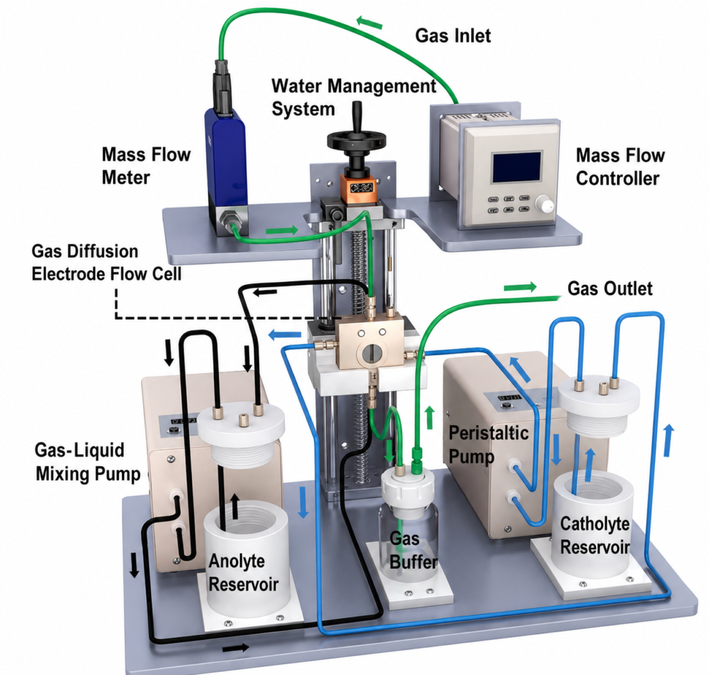
Figure 4. ANR CO₂ Reduction Complete System showing the GDE flow cell, gas-flow control, water-management, electrolyte-circulation, gas-liquid mixing, reservoirs, gas buffer, and interconnection modules. Source: ANR product documentation.
The integrated system view is useful because the modules are coupled: changing liquid flow can change pressure loss, changing reservoir height can change the hydrostatic condition, and changing gas feed can change both reactant availability and gas-side pressure drop. Accordingly, the final operating point should be established for the complete loop rather than from any single accessory setting.
The literature cited in this article supports the underlying scientific principles – reactant-distribution control, hydrodynamics, bubble transport, and pressure-dependent GDE wetting – but it does not constitute performance validation of the ANR modules themselves. Operating settings should always be established for the specific cell geometry, GDE, electrolyte, membrane, target reaction, and test configuration.
6. Conclusion
A reliable CO₂RR GDE experiment requires more than selecting the cell, membrane, and electrodes. The surrounding fluid-control hardware determines whether CO₂ delivery is reproducible, whether electrolyte circulation is stable, whether bubbles accumulate in the loop, and whether the GDE remains within a usable gas-liquid pressure window.
The selection logic is straightforward: use the mass-flow meter/controller to define the gas feed, choose PMP-1 for routine adjustable liquid circulation, choose PMP-2 when gas accumulation and bubble dispersion are central concerns, and use EC-WM when hydrostatic liquid-side adjustment is required to manage flooding or gas breakthrough. Reservoirs, gas buffering, and chemically resistant tubing then complete the controlled fluid path. The objective is not to find one universal flow rate or pump speed, but to build a stable and repeatable three-phase operating environment in which experimental data can be compared meaningfully.
References
[1] Burdyny, T.; Smith, W. A. CO₂ Reduction on Gas-Diffusion Electrodes and Why Catalytic Performance Must Be Assessed at Commercially-Relevant Conditions. Energy Environ. Sci. 2019, 12, 1442–1453. https://doi.org/10.1039/C8EE03134G
[2] Subramanian, S.; Middelkoop, J.; Burdyny, T. Spatial Reactant Distribution in CO₂ Electrolysis: Balancing CO₂ Utilization and Faradaic Efficiency. Sustainable Energy Fuels 2021, 5, 6040–6048. https://doi.org/10.1039/D1SE01534F
[3] Filippi, M.; Möller, T.; Liang, L.; Strasser, P. Understanding the Impact of Catholyte Flow Compartment Design on the Efficiency of CO₂ Electrolyzers. Energy Environ. Sci. 2023, 16, 5265–5273. https://doi.org/10.1039/D3EE02243A
[4] Baumgartner, L. M.; Koopman, C. I.; Forner-Cuenca, A.; Vermaas, D. A. When Flooding Is Not Catastrophic—Woven Gas Diffusion Electrodes Enable Stable CO₂ Electrolysis. ACS Appl. Energy Mater. 2022, 5, 15125–15135. https://doi.org/10.1021/acsaem.2c02783
[5] Nguyen, T. N.; Dinh, C.-T. Gas Diffusion Electrode Design for Electrochemical Carbon Dioxide Reduction. Chem. Soc. Rev. 2020, 49, 7488–7504. https://doi.org/10.1039/D0CS00230E
[6] Sassenburg, M.; Kelly, M.; Subramanian, S.; Smith, W. A.; Burdyny, T. Zero-Gap Electrochemical CO₂ Reduction Cells: Challenges and Operational Strategies for Prevention of Salt Precipitation. ACS Energy Lett. 2023, 8, 321–331. https://doi.org/10.1021/acsenergylett.2c01885
[7] Wakerley, D.; Lamaison, S.; Wicks, J.; Clemens, A.; Feaster, J.; Corral, D.; Jaffer, S. A.; Sarkar, A.; Fontecave, M.; Duoss, E. B.; Baker, S.; Sargent, E. H.; Jaramillo, T. F.; Hahn, C. Gas Diffusion Electrodes, Reactor Designs and Key Metrics of Low-Temperature CO₂ Electrolysers. Nat. Energy 2022, 7, 130–143. https://doi.org/10.1038/s41560-021-00973-9
[8] Angulo, A.; van der Linde, P.; Gardeniers, H.; Modestino, M. A.; Fernández Rivas, D. Influence of Bubbles on the Energy Conversion Efficiency of Electrochemical Reactors. Joule 2020, 4, 555–579. https://doi.org/10.1016/j.joule.2020.01.005
Other Blog Posts You Might Like
CO₂RR Gas Diffusion Electrode Cell Selection Guide
In carbon dioxide reduction reaction (CO₂RR) research, reactor architecture is often as important as the…
Read more
10 Years of Proven Choices: 8 Essential Tools for Electrochemical and Battery Research
Over the past decade, we’ve had the privilege of working with laboratories across different countries…
Read more
Global Trends in Solid-State Battery Development
The Evolution of Solid-State Batteries The development of solid-state batteries dates back to the 1970s.…
Read more