
How Membranes and Three-Electrode Configurations Affect Stability and Data Reliability in CO₂RR GDE Flow Cells
In carbon dioxide electroreduction (CO₂RR) research, it is natural to focus first on the catalyst itself: metal composition, facets, defects, coordination structures, particle size, loading, or interfacial modification. Catalysts are unquestionably important. However, in flow cells and gas diffusion electrode (GDE) systems, the measured Faradaic efficiency, selectivity, current density, and stability are not determined by the catalyst alone. When the same catalyst gives different results in different laboratories, reactors, or membrane, electrode, and flow-cell configurations, the discrepancy often reflects changes in the local reaction environment created by the entire integrated membrane, electrode, and fluidic environment rather than simple “catalyst failure” [1,2].
The previous two blog articles discussed CO2RR platform design, fluid management, mass-transport pathways, and GDE flow-cell selection. This third article moves closer to the core of data reliability: how membranes, working electrodes, reference electrodes, and counter electrodes should be selected. Although these components may appear to be accessories, they directly influence ion-transport pathways, local pH, product crossover, ohmic losses, potential measurement accuracy, gas-liquid-solid three-phase interface stability, and long-term material compatibility.
For a GDE flow cell, the reaction no longer follows the slow pathway typical of an H-cell, where CO2 must first dissolve in the electrolyte and then diffuse to the catalyst surface. Instead, gaseous CO2 can reach the vicinity of the catalyst layer directly through the porous electrode, shortening the transport distance and increasing local CO2 availability [1,3]. This advantage also makes the system more sensitive: small changes in membrane resistance can alter the cell voltage; differences in electrode pore structure can trigger flooding or salt precipitation; reference-electrode positioning can introduce substantial iR errors; and counter-electrode instability can introduce contamination or side reactions. Reliable CO2RR data therefore require more than catalyst formulation. They also require clear reporting of the membrane, electrodes, flow rates, electrolyte, reference system, and compensation method.
1. Membrane Selection: Ion Transport, Local pH, and Product Crossover
In a CO2RR electrolyzer, the membrane first separates the cathode and anode environments, preventing products, gases, and oxidized or reduced intermediates from directly mixing. Second, it provides an ion-conduction pathway to close the electrochemical circuit. Third, and more subtly, it helps regulate the local pH, ionic composition, and product migration near the cathode, which can be decisive for selectivity [2,4].
From the perspective of voltage distribution, the cell voltage of a practical CO2RR electrolyzer can be expressed approximately as:

Here, Ecell is the actual electrolyzer voltage, Ethermo is the thermodynamic voltage, ηcathode and ηanode correspond to cathodic and anodic kinetic overpotentials. The term iRΩ represents the overall ohmic voltage loss of the electrolyzer, where RΩ denotes the overall ohmic resistance, while ηtransport reflects mass-transport limitations. The membrane contributes substantially to RΩ through its ionic conductivity and thickness, while its ion selectivity, hydration state, and product permeability influence ηtransport and long-term material balance [2,5].
In CO2RR flow cells, the most common membranes are anion-exchange membranes (AEMs) and proton-exchange membranes (PEMs), while bipolar membranes (BPMs) are more often used for specialized reaction-environment design or mechanistic studies [2,6].
Table 1. Differences among AEM, PEM, and BPM
|
Membrane type |
Main transported ions |
Advantages |
Limitations |
Typical applications |
|
AEM |
OH⁻, HCO3⁻, CO32⁻ |
Can help maintain an alkaline or locally alkaline cathode environment; may suppress HER under appropriate operating conditions; widely used for CO, formate, and C2+ CO2RR systems. |
Carbonate formation and migration can reduce carbon utilization; liquid-product crossover and water-management issues may occur depending on membrane chemistry and operating conditions. |
Most widely used configuration in GDE flow-cell CO2RR |
|
PEM |
H+ |
High proton conductivity; mature membrane platform; can reduce carbonate transport associated with anion-conducting configurations. |
High proton availability can increase HER competition unless the cathode microenvironment is appropriately controlled. |
Acidic systems and proton-involved mechanistic studies |
|
BPM |
Interfacial water dissociation generates H+ and OH⁻ |
Enables distinct cathode and anode pH environments through interfacial water dissociation; can provide additional control over carbonate transport and the local reaction environment. |
Additional voltage losses are associated with water dissociation; more demanding interfacial stability and water-management requirements are also present. |
High-selectivity studies, tailored pH-gradient design, and advanced electrolyzer development |
Note: Membrane performance depends on polymer chemistry, ion form, thickness, pretreatment, hydration state, temperature, and operating conditions. The entries above summarize general tendencies rather than universal specifications.
Beyond these qualitative differences, membrane properties can vary substantially with polymer chemistry, ion form, thickness, pretreatment, hydration state, temperature, and measurement method. AEMs are commonly selected to support anion transport and alkaline cathode environments, whereas PEMs provide strong proton conduction. BPMs combine cation- and anion-exchange layers and use interfacial water dissociation to generate H+ and OH−, enabling greater control over the pH environments on the two sides of the membrane. Because ion-exchange capacity and conductivity can vary significantly among commercial membranes and test protocols, these properties should be reported for the specific membrane used rather than treated as universal values [2,5,6].
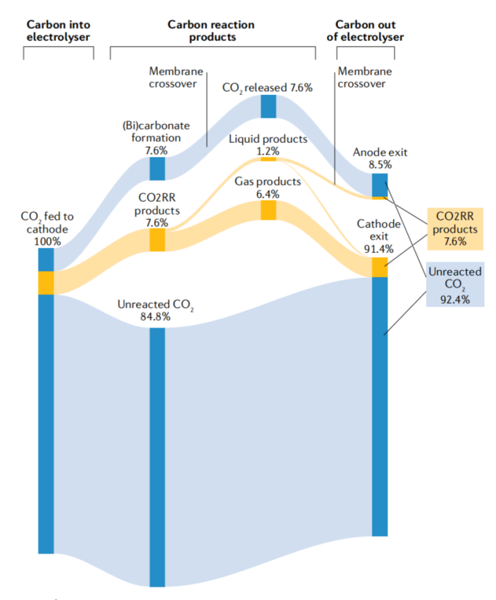
Figure 1. Representative carbon-flow pathways in a CO2 electrolyzer, illustrating how carbonate formation, membrane crossover, and product transport can affect overall carbon utilization. Reproduced with permission from Ref. [2].
Figure 1 illustrates why membrane selection affects more than ionic conductivity. During CO2RR, OH− generated near the cathode can react with CO2 to form HCO3− and CO32−. In an AEM-based system, these anionic carbon species can migrate toward the anode, contributing to carbon loss from the cathode stream. Liquid products may also cross the membrane, depending on product chemistry, membrane properties, and operating conditions. PEM- and BPM-based architectures alter these transport pathways by changing the dominant charge carriers and local pH environments. The resulting trade-offs among carbon utilization, selectivity, cell voltage, and water management are therefore strongly dependent on the complete membrane–electrode configuration rather than membrane type alone [2,5,6].
In current CO2RR research, AEMs remain the most commonly used membrane type in GDE flow cells. Nevertheless, AEMs also face challenges such as carbonate migration, decreased carbon efficiency, and liquid-product crossover [5,7]. PEMs are better suited to acidic environments or proton-involved mechanistic studies, whereas BPMs provide a route to regulate different cathode and anode pH environments, though usually with higher cell voltage and more complex water management requirements [2,6].
Recent developments in CO2 electrolysis show that membranes are evolving from simple ion-conduction media into active regulators of the reaction environment. Membrane type determines not only ion-migration direction, but also local pH, carbonate formation and migration, water management, and product crossover. It has therefore become a central factor affecting CO2RR performance and stability [2,4–7]. For example, AEM configurations typically create a distinct local reaction environment that can influence carbonate formation, salt precipitation, liquid-product crossover, and C–C coupling pathways. At the same time, they are more susceptible to salt precipitation, flooding, carbonate migration, and liquid-product crossover. PEM (or cation-exchange membrane) configurations provide stronger proton conduction and may alleviate salt precipitation to some extent, but they can also intensify HER or allow liquid products such as formate and methanol to permeate. BPMs, physically stacked AEM+PEM architectures, and porous composite membranes are all attempts to balance lower carbon loss and salt precipitation against the need to maintain favorable local pH [2,4–7].
First, what is the target product?
Membrane selection should be considered together with the catalyst, electrolyte, and intended reaction environment. For CO or formate production, AEM-based configurations are commonly used because they can support alkaline or locally alkaline cathode environments and reduce proton availability, which may suppress HER under suitable conditions. For deliberately acidic CO2RR environments, PEM- or other cation-conducting configurations may be considered, provided that HER competition is adequately controlled. For C2+ products, particularly ethylene and ethanol on Cu-based catalysts, AEMs remain widely used, but carbonate transport, liquid-product crossover, water management, and long-term salt accumulation should be evaluated at the same time [1,2,4].
Second, is the experiment aimed at short-term activity or long-term stability?
The importance of membrane-related degradation mechanisms depends strongly on the duration and purpose of the experiment. In short-duration catalyst screening or mechanistic studies, changes in membrane resistance, hydration state, or product crossover may have a smaller effect on the overall result, but they should still be considered whenever they influence product quantification, material balance, or potential measurement. In long-term stability tests, membrane resistance, salt deposition, hydration state, electrolyte composition, and product crossover should be monitored explicitly because gradual changes in these variables can become major sources of performance drift and data uncertainty [4,5,7,8].
Third, does the membrane material match the intended operating conditions?
An ideal ion-exchange membrane should provide high ionic conductivity as well as chemical stability, mechanical robustness, and dimensional stability. For AEMs, in addition to OH⁻ conductivity, alkaline stability, ion-exchange capacity (IEC), water uptake, swelling behavior, and gas-blocking ability all affect practical CO2RR performance. Thus, “AEM” or “PEM” is only a first-level classification; the specific brand, model, and pretreatment protocol must still be selected according to the experimental conditions.
Data comparability and experimental records
For studies that require cross-laboratory comparison or long-term data accumulation, simply stating that an “AEM” or “PEM” was used is not sufficient. Membrane model, thickness, pretreatment method, ion-form conversion procedure, soaking solution, and post-operation state can all affect membrane conductivity, cell voltage, and product selectivity. These details should therefore be fully reported in laboratory records and publications to improve reproducibility and comparability. Otherwise, even membranes of the same general type may lead to noticeably different results because of differences in pretreatment or hydration state.
2. Working Electrode Selection: More Than a Catalyst Support
In a GDE flow cell, the working electrode serves not only as an electron-conducting pathway, but also as the structural basis for forming the gas-liquid-solid three-phase interface. In a traditional H-cell, glassy carbon mainly functions as an inert conductive substrate. In a GDE system, however, porous conductive substrates such as carbon paper, carbon cloth, nickel foam, and other gas-permeable supports can directly affect CO2 delivery, water management, local salt concentration, and current distribution [1,3,10]. By contrast, glassy carbon is a dense, nonporous substrate more commonly used for fundamental electrochemical studies and is not typically employed as a conventional GDE substrate.
A simple limiting-current expression helps illustrate why the working electrode matters:
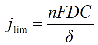
Here, jlim is the limiting current density, n is the number of transferred electrons, F is the Faraday constant, D is the diffusion coefficient, C is the reactant concentration, and δ is the diffusion-layer thickness. The core advantage of a GDE is that gas-phase CO2 supply shortens the effective transport distance and increases local CO2 availability [1,3]. Whether this advantage can be maintained depends on whether the electrode pores can deliver gas without becoming fully flooded by electrolyte.
Table 2. Common working-electrode substrates for CO2RR
|
Working-electrode substrate |
Typical structural features |
Main advantages |
Main limitations |
Typical applications |
|
Carbon paper |
Thickness of about 0.19–0.30 mm; porosity of about 75–85%; high flatness |
Good gas-diffusion performance; uniform catalyst coating; easy to construct standardized GDEs |
Susceptibility to flooding, drying, or salt accumulation depends strongly on wettability, microporous-layer structure, pressure balance, and operating conditions; mechanically less flexible than carbon cloth. |
Catalyst screening, CO and C2+ product evaluation, and medium-to-high-current-density GDE testing |
|
Carbon cloth |
Thickness of about 0.30–0.45 mm; porosity of about 70–80%; woven fiber structure |
Good mechanical flexibility and tolerance to repeated wet–dry operation; useful when structural durability is important. |
Higher surface roughness; more difficult to control catalyst-coating uniformity |
Long-term stability tests, medium-to-high-current-density operation, and durability studies |
|
Glassy carbon |
Dense nonporous structure; thickness of about 1–3 mm |
High chemical stability; low background current; suitable for studying intrinsic catalyst activity |
No gas-diffusion pathway; unsuitable for medium-to-high-current-density GDE systems |
Not typically used as a GDE substrate; mainly relevant for fundamental comparison outside GDE flow-cell operation |
|
Nickel foam |
Three-dimensional porous conductive network; porosity of about 95–98%; thickness of about 0.5 mm |
Excellent conductivity; high specific surface area; suitable for medium-to-high-current-density operation and strongly alkaline systems |
The metallic substrate may participate in electrochemical reactions or undergo surface reconstruction, oxidation, or corrosion; therefore, substrate contributions must be distinguished from catalyst activity. |
Strongly alkaline systems, medium-to-high-current-density studies, and electrode-structure development |
Note: Structural parameters are representative values for commonly used commercial substrates. Actual properties vary with manufacturer, substrate architecture, surface treatment, catalyst-layer integration, and cell-assembly conditions.
Different working-electrode substrates affect not only electron transport, but also gas diffusion, water management, and three-phase interface stability (Table 2). For most GDE flow-cell CO2RR studies, carbon paper and carbon cloth remain the most common choices. Glassy carbon is better suited to fundamental electrochemical studies, while nickel foam is often used in strongly alkaline and medium-to-high-current-density systems. Importantly, the role of the working electrode has expanded from a simple catalyst support to a regulator of the local reaction environment; pore structure, wettability, and mechanical stability all influence the final experimental outcome [3,9,10].
Electrode design is shifting from “catalyst support” to “local reaction environment regulator”
In traditional electrochemical tests, the working electrode is often viewed as a substrate that carries the catalyst and conducts electrons. In GDE flow-cell CO2RR, however, the working electrode itself has become an important engineering unit for regulating the local reaction environment. A complete GDE typically includes a gas diffusion layer (GDL), a microporous layer (MPL), and a catalyst layer (CL). Together, these structures influence CO2 transport pathways, local ion concentration, wetting state, bubble detachment, and three-phase interface stability. Therefore, improved catalyst performance may arise not only from active sites, but also from electrode-structure optimization that enhances local CO2 concentration, mass transport, and interfacial stability. When comparing catalyst results, researchers should report not only catalyst composition and loading, but also the GDL/MPL structure, electrode-substrate type, and electrode-preparation method; otherwise, data from different studies are difficult to compare directly [3,9,10,14].
Two common failure modes: flooding and salt precipitation
GDE instability often appears as increasing cell voltage, drifting product selectivity, enhanced HER, abnormal gas-line pressure, or local drying. One typical mechanism is flooding, in which electrolyte intrudes into pores that should remain available for gas transport, blocking the CO2 transport pathway. Once CO2 supply from the gas side becomes unstable, local CO2 concentration decreases, HER becomes more competitive, and both current efficiency and stability suffer [3,10].
Another common issue is salt precipitation. CO2RR experiments commonly use KHCO3, KOH, or other salt-containing electrolytes. At high current densities, local pH, ion migration, and water flux change the local salt concentration. When salts deposit inside the GDE pores or at the membrane/electrode interface, both gas transport and ion conduction deteriorate, leading to increased voltage, local hot spots, interfacial delamination, and selectivity fluctuations [5,10].
Therefore, working-electrode selection should not be based only on whether the substrate is conductive or can hold catalyst ink. More practical questions include: What is the target current density? Is gas-phase CO2 supply required? Is the electrolyte prone to salt precipitation? Will the test last 30 minutes or 100 hours? Does the setup need to work together with water-management systems, gas-liquid mixing pumps, mass-flow controllers, and pressure balancing in a GDE flow cell?
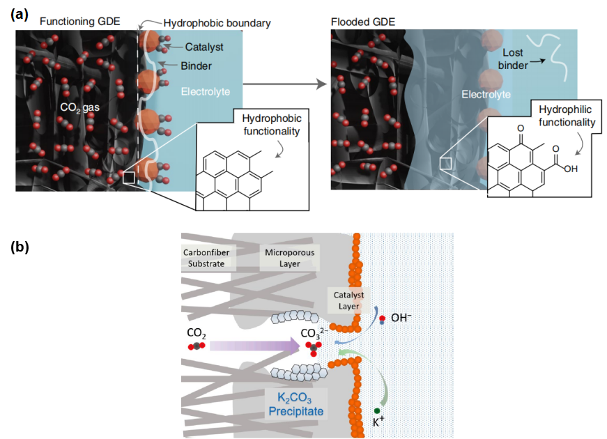
Figure 2. Typical failure mechanisms in gas diffusion electrodes (GDEs) during CO2 electroreduction. (a) Flooding in a GDE. Reproduced with permission from Ref. [11]. (b) Salt precipitation in a flow-cell CO2RR system. Reproduced with permission from Ref. [12].
As shown in Fig. 2, the two most common failure mechanisms during long-term GDE operation are flooding and salt precipitation. Flooding usually originates from gradual electrolyte intrusion into pores intended for gas transport, partially or completely blocking CO2 diffusion pathways. This lowers the local CO2 concentration and strengthens HER competition. Meanwhile, under medium-to-high-current-density conditions, OH– generated at the cathode continuously reacts with CO2 to form bicarbonate and carbonate species, which can further combine with cations such as K+ to form deposits. As salt crystals accumulate in the catalyst layer, microporous layer, and gas diffusion layer, both gas-transport and ion-transport resistances increase, eventually causing higher cell voltage, product selectivity fluctuations, and reduced long-term stability. Although flooding and salt precipitation arise through different pathways, both disrupt the stable three-phase interface inside the GDE and weaken CO2 mass transport, making them key engineering challenges for durable medium-to-high-current-density CO2RR [11,12].
3. Reference Electrode Selection: The Basis for Reliable Potential Measurement
One common misconception in CO2RR is to treat the potential displayed by the workstation as the true potential at the catalyst surface. In reality, current passes through electrolyte, membrane, pores, and interfaces, producing uncompensated resistance (Ru). Reference-electrode position, salt-bridge structure, filling solution, and compatible pH range all affect the measured potential [13].
The potential drop associated with uncompensated resistance can be approximated as:
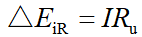
Here, ΔEiR is the potential drop associated with uncompensated resistance, I is the total cell current, and Ru is the uncompensated resistance specifically between the working and reference electrodes. Unlike RΩ, which denotes the overall ohmic resistance of the electrolyzer in the cell-voltage expression above, Ru refers specifically to the uncompensated resistance relevant to the working-electrode potential measurement. As operating current increases, even modest uncompensated resistance can produce a substantial potential error. Because the magnitude of the iR error depends on both the total current and Ru, and the total current scales with electrode area at a given current density, the iR-compensation method should be reported together with the potential data when comparing across different flow-cell configurations [13].
Table 3. Common reference electrodes used in CO2RR
|
Reference electrode |
Typical compatible systems |
Main advantages |
Main limitations |
Typical applications |
|
Ag/AgCl |
Neutral and acidic aqueous solutions; KHCO3 electrolyte systems |
Most widely used; stable potential; broad commercial availability; easy comparison with literature data |
Potential depends on filling-solution concentration, temperature, and electrolyte composition; regular calibration is recommended |
H-cell testing, neutral-electrolyte flow-cell testing, catalyst screening |
|
Ag/Ag⁺ |
Nonaqueous organic electrolyte systems |
Suitable for organic solvents and wide potential-window studies; useful for nonaqueous CO2 electroreduction mechanisms |
Potential strongly depends on solvent, supporting electrolyte, and Ag+ concentration; calibration against an internal standard (e.g., Fc/Fc+) is recommended |
Nonaqueous CO2RR, mechanistic studies, fundamental electrochemical research |
|
Hg/HgO |
Alkaline aqueous solutions such as KOH |
Good stability under high-pH conditions; clear potential-conversion relationship in alkaline systems |
Not suitable for acidic environments; mercury-based electrode handling and maintenance requirements must be considered |
AEM flow cells, strongly alkaline electrolytes, medium-to-high-current-density CO2RR |
Note: Actual performance depends on electrolyte composition, cell architecture, and operating conditions.
Regardless of the reference electrode selected, reports should specify the reference type, filling solution, salt-bridge configuration, calibration method, potential-conversion equation, and iR-compensation approach. For cross-literature comparison, potentials should preferably be converted to reversible hydrogen electrode (RHE) or another clearly defined scale, and online or offline iR compensation should be stated. Otherwise, a claim such as “high selectivity at -0.8 V vs RHE” may mask differences in Ru and reference-electrode placement between experiments.
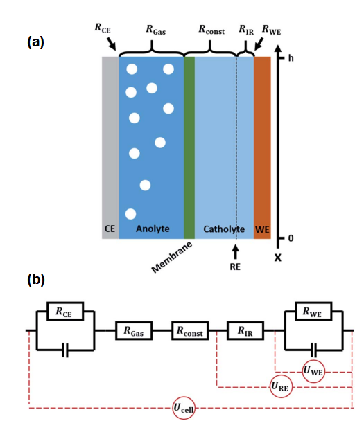
Figure 3. Schematic illustration of resistance gradients and reference-electrode positioning effects in a CO2RR flow cell. Reproduced with permission from Ref. [13].
As shown in Fig. 3, under medium-to-high-current-density operation in flow cells, continuous gas evolution at the electrode surface changes the local electrolyte conductivity through bubble accumulation and flow-field distribution, creating nonuniform resistance along the channel. When the reference electrode is located farther from the working electrode, the measurement pathway includes a longer uncompensated resistance, and the measured potential may deviate from the true potential at the working-electrode surface. This error increases with current density. Therefore, in CO2RR flow-cell experiments, the reference electrode should be placed as close as practical to the working electrode, while the Ru measurement method and iR-compensation protocol should be reported to improve data comparability [13].
4. Counter Electrode Selection: An Often Overlooked Variable
The counter electrode closes the electrochemical circuit and supports the anodic reaction, most commonly the oxygen evolution reaction (OER). Although CO2RR studies primarily focus on the cathode, the counter electrode should not be assumed to be inert. Its catalytic activity, effective area, stability, and possible dissolution products can influence anodic polarization, overall cell voltage, and contamination of the cathode compartment. Pt-based counter electrodes are convenient for many short-duration laboratory experiments, but Pt dissolution and subsequent deposition on the cathode can become a concern in contamination-sensitive or extended tests. For longer-duration or higher-current operation, the counter electrode should therefore be selected on the basis of OER activity, chemical stability, effective area, and compatibility with the electrolyte and membrane [15,16].
Table 4. Common counter electrodes used in CO2RR experiments
|
Counter electrode |
Compatible systems |
Main advantages |
Main limitations |
Typical applications |
|
Pt wire |
Acidic, neutral, and alkaline aqueous solutions; some organic systems |
Excellent conductivity; high electrochemical stability; low polarization; easy to use |
Limited surface area; anodic polarization may occur at high current density; long-term operation may involve Pt dissolution and cathode contamination |
Catalyst screening, H-cell testing, short-term electrochemical experiments |
|
Pt sheet |
Acidic, neutral, and alkaline aqueous solutions; some organic systems |
Larger effective area; more uniform current distribution; suitable for higher-current operation |
Higher cost; long-term operation still carries a risk of Pt migration and contamination |
Flow-cell testing and medium-to-high-current-density CO2RR experiments |
|
Pt mesh |
Acidic, neutral, and alkaline aqueous solutions; some organic systems; high-temperature and high-pressure conditions |
Large surface area; low anodic polarization; good bubble detachment; suitable for medium-to-high-current-density operation |
High cost; Pt crossover contamination should be considered in long-term stability tests |
Flow cells, medium-to-high-current-density testing, long-term electrolysis |
|
Graphite rod |
Neutral and alkaline aqueous solutions; some organic systems |
Low cost; lower risk of metal contamination; suitable for extended operation |
May oxidize, shed particles, or be consumed at high anodic potentials; not absolutely inert |
Long-term stability testing, metal-contamination-sensitive studies, alkaline CO2RR systems |
|
Carbon-based counter electrode |
Neutral and alkaline systems; some organic electrolytes |
Low metal-contamination risk; readily available materials |
Limited oxidation resistance; structural degradation may occur during long-term operation |
Intrinsic-activity studies, contamination-control experiments, mechanistic studies |
|
Ti mesh |
Neutral and alkaline aqueous systems; contamination-sensitive electrochemical testing |
Good corrosion resistance; good mechanical stability; low risk of noble-metal contamination |
Lower OER activity than catalyst-coated Ti or noble-metal-based anodes; anodic passivation can increase interfacial resistance and polarization |
Contamination-sensitive studies, moderate-current electrolysis, and support substrates for catalyst-coated OER anodes |
|
IrO2-coated Ti mesh (DSA-type) |
Flow cells and CO₂ electrolyzers; compatibility depends on electrolyte and coating composition |
High OER activity; good mechanical stability; suitable for sustained medium-to-high-current-density operation |
Higher cost; long-term performance depends on catalyst loading, coating quality, and operating conditions |
Long-term electrolysis, medium-to-high-current-density CO₂RR testing, and electrolyzer scale-up |
Note: Actual stability and contamination risks vary with operating conditions and cell configuration.
Counter-electrode selection can be summarized as follows: for short-term screening, prioritize stability, convenience, and low polarization; for long-term operation, prioritize material compatibility and contamination control; for medium-to-high-current-density tests, prioritize sufficient area and efficient bubble detachment; for mechanistic studies, prioritize minimizing potential interference from the anode material.
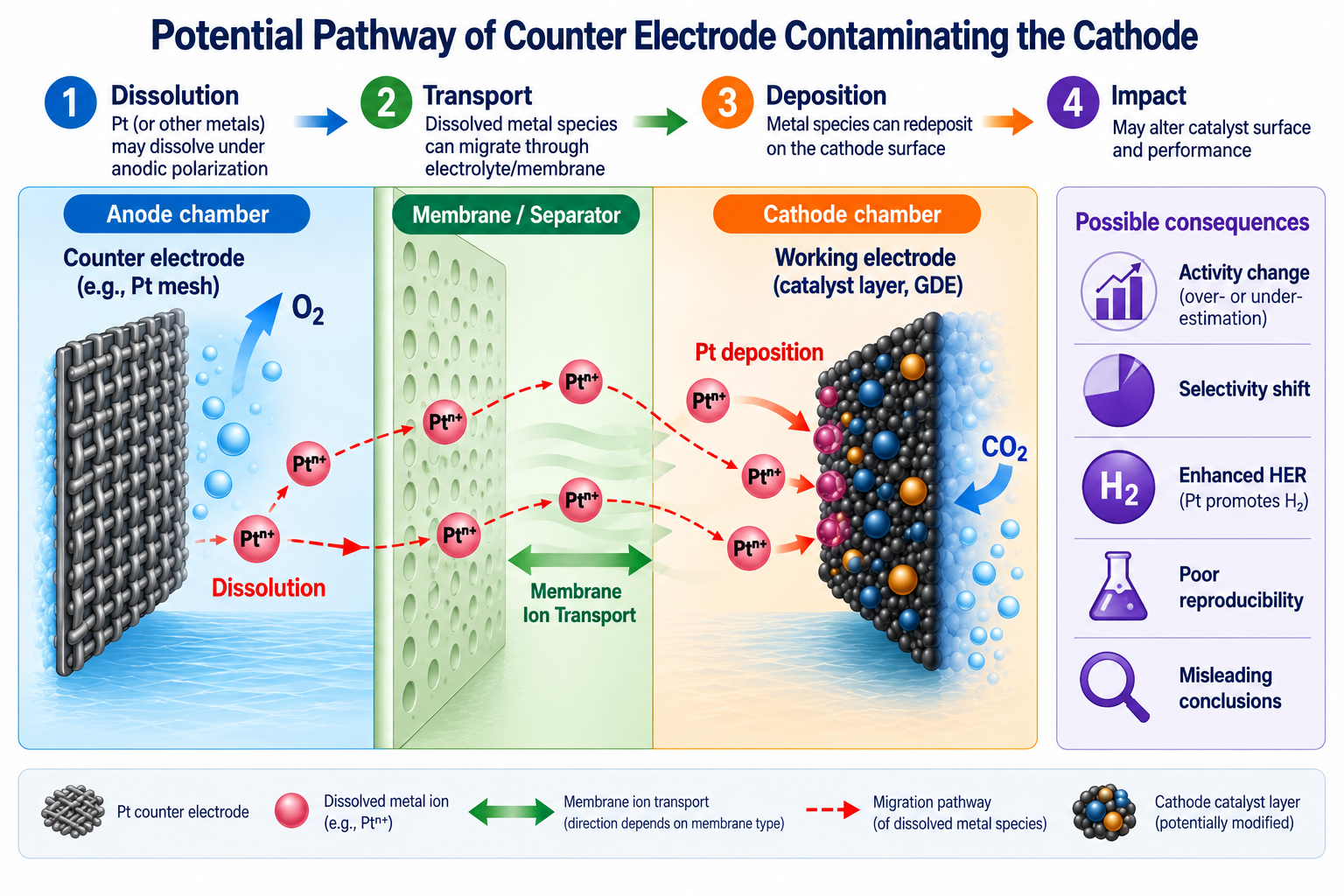
Figure 4. Possible counter-electrode contamination pathways in CO2RR systems. Based on Refs. [15,16].
As shown in Fig. 4, counter-electrode materials may not be completely inert under certain conditions. Taking a Pt counter electrode as an example, metal species may dissolve at high anodic potentials or during long-term operation, migrate through the cell, and redeposit on the working-electrode surface, thereby changing the catalyst composition or electrochemical behavior. For CO2RR studies aimed at evaluating intrinsic activity, even trace metal deposition can affect product selectivity, current response, and stability. Counter-electrode selection and potential contamination risks should therefore be explicitly recorded and evaluated.
It should be emphasized that Fig. 4 only illustrates potential pathways for counter-electrode contamination of the cathode and is not a quantitative result for any specific system. The actual degree of contamination depends on counter-electrode material, electrolyte composition, membrane type, current density, operation time, and reactor architecture. In long-term stability tests or studies sensitive to metal contamination, blank experiments, post-operation characterization, and elemental analysis such as ICP-MS, XPS, or SEM-EDS are recommended to determine whether the counter electrode interferes with the results and to improve reliability and reproducibility [15,16].
5. Practical Selection Matrix: From Catalyst Screening to Long-Term Stability
The following combinations can serve as starting points for CO2RR GDE flow-cell experiments. Actual selection should still be adjusted according to target product, electrolyte pH, current density, reactor geometry, flow rate, pressure balance, and analytical method.
Table 5. Illustrative Starting Configurations for Membrane and Three-Electrode Selection in CO2RR
|
Experimental objective |
Example membrane |
Example working electrode |
Example reference electrode |
Example counter electrode |
Selection rationale |
|
Catalyst screening |
AEM |
Carbon paper |
Ag/AgCl |
Pt wire |
Provides a simple and reproducible starting point for catalyst evaluation while minimizing unnecessary complexity in membrane and electrode configuration. |
|
Standard GDE testing |
AEM |
Carbon paper |
Ag/AgCl |
Pt mesh |
Balances CO2 mass transport, three-phase interface stability, and data comparability |
|
Medium-to-high-current-density GDE testing |
AEM |
Carbon paper or carbon cloth |
Hg/HgO for strongly alkaline systems; calibrated Ag/AgCl for neutral/mild conditions |
Pt mesh or graphite |
Focus on local pH, membrane resistance, gas-liquid pressure balance, and flooding |
|
Long-term stability testing |
AEM; evaluate BPM if needed |
Carbon cloth or stable GDE |
Hg/HgO or calibrated Ag/AgCl |
Graphite where carbon corrosion is acceptable, or another stable low-contamination OER electrode |
Prioritizes reduction of material contamination, salt precipitation, and interfacial drift |
Table 5 is intended as a decision-support framework rather than a universal prescription. The appropriate configuration depends on the target product, catalyst, electrolyte, current-density range, cell architecture, and duration of operation. A practical selection process should first define the desired reaction environment and operating regime, then evaluate membrane transport, GDE wettability, reference-electrode accuracy, counter-electrode compatibility, carbonate management, product crossover, and contamination risk. Membrane and electrode selection should therefore be treated as a system-level optimization problem rather than as a choice based on any single component.
6. Data Comparability Is Equally Important
In recent years, the CO2RR community has placed increasing emphasis on standardized reporting. Reporting only Faradaic efficiency, current density, and product distribution is no longer sufficient for meaningful cross-literature comparison. To improve reproducibility, researchers should report membrane, electrode, and operating conditions as completely as possible. Many apparently contradictory catalyst-performance trends may originate from incomplete descriptions of experimental conditions rather than from the catalyst itself. High-quality CO2RR research should therefore pursue not only higher FE or larger current density, but also experimental conditions that can be reproduced and compared [15,16].
CO2RR results are not determined by the catalyst alone. They emerge from the combined effects of the catalyst, membrane, working electrode, reference electrode, counter electrode, fluid management, and reactor architecture. The membrane governs ion transport, local pH, product crossover, and cell voltage; the working electrode determines the three-phase interface, CO2 supply, flooding, and salt-precipitation risks; the reference electrode determines whether the measured potential is reliable; and the counter electrode affects anodic polarization, material compatibility, and possible contamination.
Therefore, when building and optimizing a CO2RR platform, the membrane and three-electrode system should be systematically recorded and controlled as key experimental parameters rather than treated as interchangeable auxiliary components. A high-quality CO2RR data set should report at least the membrane model and pretreatment, working-electrode substrate and catalyst loading, reference-electrode type and calibration method, counter-electrode material, iR-compensation method, electrolyte composition, CO2 flow rate, liquid flow rate, reactor geometry, and stability-test duration.
Once this information is systematically documented, differences among experiments become easier to interpret, and catalyst performance can be evaluated more fairly. In other words, reliable CO2RR research is not only about achieving higher FE or larger current density; it is about establishing a reproducible, comparable, and diagnosable CO2RR GDE platform.
As CO2RR systems continue to move from laboratory demonstrations toward industrially relevant operation, careful control and reporting of membranes, GDE substrates, electrode configuration, flow conditions, and reference/counter-electrode setup will become increasingly important for generating reliable, reproducible, and transferable performance data.
References
[1] Burdyny, T.; Smith, W. A. CO2 reduction on gas-diffusion electrodes and why catalytic performance must be assessed at commercially-relevant conditions. Energy & Environmental Science, 2019, 12, 1442–1453. https://doi.org/10.1039/C8EE03134G
[2] Lees, E. W.; Mowbray, B. A. W.; Parlane, F. G. L.; Berlinguette, C. P. Gas diffusion electrodes and membranes for CO2 reduction electrolysers. Nature Reviews Materials, 2022, 7, 55–64. https://doi.org/10.1038/s41578-021-00356-2
[3] Hernandez-Aldave, S.; Andreoli, E. Fundamentals of Gas Diffusion Electrodes and Electrolysers for Carbon Dioxide Utilisation: Challenges and Opportunities. Catalysts, 2020, 10, 713. https://doi.org/10.3390/catal10060713
[4] Chang, H.-M.; Zenyuk, I. V. Membrane electrode assembly design to prevent CO2 crossover in CO2 reduction reaction electrolysis. Communications Chemistry, 2023, 6, 2. https://doi.org/10.1038/s42004-022-00806-0
[5] Yang, Y.; Shi, Y.; Yu, H.; Zeng, J.; Li, K.; Li, F. Mitigating carbonate formation in CO2 electrolysis. Next Energy, 2023, 1, 100030. https://doi.org/10.1016/j.nxener.2023.100030
[6] Petrov, K. V.; Koopman, C. I.; Subramanian, S.; Koper, M. T. M.; Burdyny, T.; Vermaas, D. A. Bipolar membranes for intrinsically stable and scalable CO2 electrolysis. Nature Energy, 2024, 9, 932–938. https://doi.org/10.1038/s41560-024-01574-y
[7] Yan, J.; Wang, Y.; Xu, T. Ion leakage in bipolar membranes undermines CO2 electrolysis. Nature Chemical Engineering, 2026, 3, 91–93. https://doi.org/10.1038/s44286-025-00325-4
[8] Liu, W.; Dunne, H.; Ballotta, B.; Massie, A. A.; Ghaani, M. R.; McKelvey, K.; Dooley, S. CO2 Loss into Solution: An Experimental Investigation of CO2 Electrolysis with a Membrane Electrode Assembly Cell. ACS Applied Energy Materials, 2024, 7, 7712–7723. https://doi.org/10.1021/acsaem.4c01101
[9] Higgins, D.; Hahn, C.; Xiang, C.; Jaramillo, T. F.; Weber, A. Z. Gas-Diffusion Electrodes for Carbon Dioxide Reduction: A New Paradigm. ACS Energy Letters, 2019, 4, 317–324. https://doi.org/10.1021/acsenergylett.8b02035
[10] Yang, K.; Kas, R.; Smith, W. A.; Burdyny, T. Role of the Carbon-Based Gas Diffusion Layer on Flooding in a Gas Diffusion Electrode Cell for Electrochemical CO2 Reduction. ACS Energy Letters, 2021, 6, 33–40. https://doi.org/10.1021/acsenergylett.0c02184
[11] Wu, Y.; Rabiee, H.; Zhao, X. S.; Wang, G.; Jiang, Y. Insights into electrolyte flooding in flexible gas diffusion electrodes for CO2 electrolysis: from mechanisms to effective mitigation strategies. Journal of Materials Chemistry A, 2024, 12, 14206–14228. https://doi.org/10.1039/D4TA01994F
[12] Chen, Y.; Wu, B.; Qian, L. Proton Pool for the Mitigation of Salt Precipitate Enhancing CO2 Electroreduction in a Flow Cell. Catalysts, 2024, 14, 807. https://doi.org/10.3390/catal14110807
[13] Jännsch, Y.; Hämmerle, M.; Leung, J. J.; Simon, E.; Fleischer, M.; Moos, R. Gas evolution in electrochemical flow cell reactors induces resistance gradients with consequences for the positioning of the reference electrode. RSC Advances, 2021, 11, 28189–28197. https://doi.org/10.1039/D1RA05345K
[14] Rabiee, H.; Ge, L.; Zhang, X.; Hu, S.; Li, M.; Yuan, Z. Gas diffusion electrodes (GDEs) for electrochemical reduction of carbon dioxide, carbon monoxide, and dinitrogen to value-added products: a review. Energy & Environmental Science, 2021, 14, 1959–2008. https://doi.org/10.1039/D0EE03756G
[15] Seger, B.; Robert, M.; Jiao, F. Best practices for electrochemical reduction of carbon dioxide. Nature Sustainability, 2023, 6, 236–238. https://doi.org/10.1038/s41893-022-01034-z
[16] Pander, J. E., III; Ren, D.; Yeo, B. S. Practices for the collection and reporting of electrocatalytic performance and mechanistic information for the CO2 reduction reaction. Catalysis Science & Technology, 2017, 7, 5820–5832. https://doi.org/10.1039/C7CY01785E
Other Blog Posts You Might Like

10 Years of Proven Choices: 8 Essential Tools for Electrochemical and Battery Research
Over the past decade, we’ve had the privilege of working with laboratories across different countries…
Read more
Science Shopping Spree Stumbles: The Biggest Procurement Hurdles of 2023
The Research Gate Lab Purchasing Report 2018 found that when it comes to purchasing lab…
Read more
Optimizing Research Efficiency with ANR’s Core Solutions
In material science research, efficiency is critical. Researchers are constantly managing experimental setups, conducting tests,…
Read more