
Building a Complete CO₂RR GDE System: Integration and Published Applications
A reliable CO₂ reduction reaction (CO₂RR) experiment requires more than selecting a GDE flow cell. The cell must operate together with the membrane and electrodes, CO₂ delivery, electrolyte circulation, pressure and water management, electrochemical control, and product analysis.
The previous articles in this series discussed these elements individually. This final article brings them together: first by showing what a complete GDE-based platform contains, and then by linking system choices to published CO₂RR applications using GDE platforms corresponding to the current Beyond Battery® EC-GDE Series.
1. Why a GDE Cell Alone Is Not a Complete CO₂RR Experiment
A GDE changes how CO₂ reaches the catalyst, but the cell alone does not define the experimental environment. Gas delivery, electrolyte circulation, membrane and electrode configuration, pressure balance, electrochemical control, and product analysis all influence what is measured. The experiment therefore needs to be designed as a coordinated platform rather than as a reactor plus accessories.
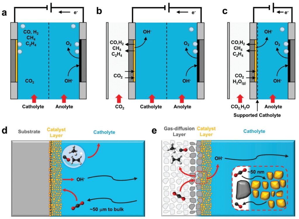
Figure 1. Comparison of conventional H-cell and gas-diffusion-electrode configurations and their CO₂ mass-transport pathways. Adapted from Ref. [9], Fig. 2 (CC BY 3.0).
Table 1. Representative GDE Flow Cell versus conventional H-cell comparison.
|
Parameter |
GDE Flow Cell |
Conventional H-Cell |
|
Current density |
> 200 mA cm⁻² |
5–20 mA cm⁻² |
|
CO₂ feed mode |
Direct gas-phase feed to GDE |
CO₂ dissolved in electrolyte |
|
Electrolyte compatibility |
Broad pH compatibility (0–14*) |
Limited by cell materials |
|
Product handling |
Continuous gas and liquid collection |
Batch operation; product accumulation |
|
Scalability |
Modular and scalable |
Limited scalability |
Source: ANR Technologies, CO₂ Reduction Complete System. Values are representative; *pH compatibility depends on membrane, electrode, sealing, and wetted-path materials.
2. What the Complete System Actually Contains
The ANR CO₂ Reduction Complete System is organized into three functional modules. The value of the system is not simply the number of components, but the ability to coordinate reaction conditions, gas and liquid delivery, and the pressure environment around the GDE.
Table 2. Functional modules of the ANR CO₂ Reduction Complete System.
|
Module |
Core components |
Primary role |
|
Electrolytic Reaction |
|
Creates the controlled electrochemical reaction environment |
|
Fluid Transfer & Control |
|
Controls gas/liquid delivery, circulation, bubble management, and pressure balance |
|
Fluid Storage & Interconnection |
|
Provides storage, buffering, and stable interconnection between modules |
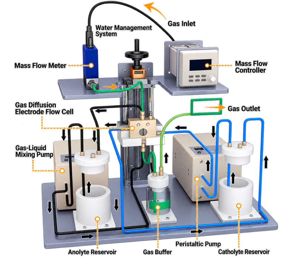
Figure 2. Integrated CO₂RR GDE platform showing the main reaction, fluid-control, and storage/interconnection components. Source: ANR Technologies, CO₂ Reduction Complete System.
2.1 Fluid-Control Functions
Table 3. Core fluid-control functions and selected specifications.
|
Component |
Selected specification |
Why it matters |
|
EC-MFM + EC-MFC |
0–500 sccm / 0–30 SLM; ±1% F.S.; response ≤2 s; max. working pressure 1 MPa; RS485/RS232 (Modbus RTU) |
Reproducible CO₂ flow setting, monitoring, and host-computer communication |
|
PMP-1 |
0–35 mL min⁻¹; 0–200 rpm; forward/reverse; full-speed fill/flush |
Routine electrolyte circulation and line handling |
|
PMP-2 |
140–170 mL min⁻¹; 90 kPa; high-shear gas dispersion |
Bubble removal and gas–liquid mixing where required |
|
EC-WM |
260 mm effective stroke; optional electric remote control |
Adjusts relative GDE-cell height to balance gas/liquid pressure and reduce flooding or gas breakthrough |
The EC-WM is particularly distinctive because it manages pressure balance by changing the relative height of the GDE flow cell. This changes the hydrostatic contribution on the liquid side and helps maintain a stable gas–liquid–solid interface. It should not be treated as a universal back-pressure regulator; gas flow, tubing resistance, pump conditions, and the cell flow field also contribute to the overall pressure balance.
A published EC-GDE4 study by Qing et al. used a peristaltic pump for catholyte circulation and a gas–liquid mixed-flow pump for anolyte circulation [6], illustrating how the two liquid loops can be configured independently for a specific reaction system.
2.2 Electrode, Membrane and Materials Options
The reaction module can be configured with R1038 or PK-1038 Ag/AgCl, 4038 Ag/Ag⁺, or Hg-1038 Hg/HgO reference electrodes; Pt wire/sheet/mesh or graphite counter electrodes; carbon paper, carbon cloth, glassy carbon, or nickel foam working-electrode substrates; and Nafion N-117 or Fumasep FAA-3-50 membranes. Across the portfolio, cell and wetted-path materials include PEEK, PTFE, PMMA, and titanium for different electrolyte environments. Supplied components vary by model and experimental configuration; some configurations, including EC-GDE6 and EC-GDE-PEC2, require customer-supplied electrodes, so the final electrode configuration should be confirmed for the selected model.
3. Choosing the GDE Platform
The current EC-GDE1–EC-GDE6 series covers entry-level, standard, visualized, short-gap, modular, and ultra-short-gap architectures. Typical active areas are 1 and 4 cm², with other areas customizable according to the selected model and experimental requirements. Selection should be based on the experimental objective and the complete operating environment rather than electrode gap or active area alone.
Table 4. Current EC-GDE1–EC-GDE6 platform positioning.
|
Model |
Electrode gap |
Key design |
Research positioning |
|
EC-GDE1 |
25 mm |
PEEK; quick-opening three-chamber design |
Entry-level GDE testing and catalyst screening |
|
EC-GDE2 |
20 mm |
PMMA / PTFE / PEEK; general flow-cell platform |
Rapid feasibility validation and general catalyst evaluation |
|
EC-GDE3 |
7 mm |
PEEK + quartz observation window |
Visualized GDE studies and mechanistic investigation |
|
EC-GDE4 |
3 mm |
PEEK + quartz observation window |
Short-gap, medium-to-high-current-density catalyst evaluation |
|
EC-GDE5 |
1.2 mm |
Ti + PEEK; four modes: GDE / solid electrolyte / MEA / metal-air; 45° RE port |
Multimode reactor studies and advanced GDE research |
|
EC-GDE6 |
0.4 mm |
Ti + PEEK; serpentine gas field; customer-supplied WE and IrO₂ CE |
Demanding medium-to-high-current-density and long-duration studies |
Beyond EC-GDE1–EC-GDE6, the current catalogue also includes specialized EC-GDE-SE1–SE4 platforms for solid-electrolyte and high-purity liquid-product studies, EC-GDE-1LC / EC-GDE-2LC for large-liquid-chamber operation, and EC-GDE-PEC1 / EC-GDE-PEC2 for dedicated photoelectrochemical studies. These are complementary product families rather than replacements for the six core GDE models.
4. Published Applications: Overview and Representative Cases
Published studies using GDE platforms corresponding to the current EC-GDE portfolio show how reactor architecture can be combined with different catalysts, membranes, electrolytes, flow conditions, and analytical systems. The performance values summarized in this section are literature-reported results obtained under the specific experimental conditions of each study and should not be interpreted as guaranteed specifications of current products. The matrix below provides an overview first; only three representative cases are expanded afterward to avoid repeating the same literature twice.
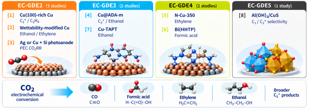
Figure 3. Published applications corresponding to the current EC-GDE portfolio and representative CO₂RR product targets. Numbers correspond to Refs. [1]–[8]; catalyst illustrations are schematic.
Table 5. Published CO₂RR Applications Corresponding to the Current EC-GDE Series.
|
Platform |
Study / catalyst |
Representative conditions |
Focus |
Representative result |
|
EC-GDE2 |
[1] Zhang 2021 |
2 M KOH; AEM; CO₂ 10 sccm |
C₂H₄ / C₂+ |
C₂H₄ FE 58.6%; C₂+ FE 86.6% |
|
EC-GDE2 |
[2] Lin 2023 |
1 M KOH; AEM; CO₂ 20 sccm |
Ethanol / ethylene |
EtOH FE 53.7%; C₂+ FE 80.3% at 400 mA cm⁻² |
|
EC-GDE2 |
[3] Liu 2022 |
1 M KOH; AM 1.5G |
PEC CO₂RR |
CO FE ≈90%; C₂+ FE ≈53% |
|
EC-GDE3 |
[4] Bai 2026 |
1 M KOH; Nafion 117; CO₂ 30 sccm |
C₂+ / ethanol / stability |
C₂+ FE 86.8%; after 42 h at 200 mA cm⁻², C₂+ FE remained >70.8% (81.6% of initial FE retained) |
|
EC-GDE4 |
[5] Tao 2023 |
1 M KOH; AEM; CO₂ 30 mL min⁻¹ |
Ethylene |
C₂H₄ FE 73.2%; |jC₂H₄| = 700.8 mA cm⁻² |
|
EC-GDE4 |
[6] Qing 2025 |
KHCO₃-based catholyte; BPM; CO₂ 30 sccm |
Formic acid |
FEHCOOH >96%; jHCOOH ≈305 mA cm⁻² |
|
EC-GDE3 |
[7] Chen 2024 |
1 M KOH; AEM; CO₂ 20 sccm |
Ethanol |
EtOH FE 54.3 ± 3%; total current density 429 mA cm⁻² |
|
EC-GDE5 |
[8] Zhou 2025 |
1 M KOH |
C₁ / C₂+ selectivity; stability |
HCOOH FE 37% at −0.8 V; C₂+ FE 54% and jC₂+ 254 mA cm⁻² at −1.2 V; 14,400 s operation |
Note: Gas-flow units are retained as reported in the source papers, with “sccm” capitalization standardized. EC-GDE1 and EC-GDE6 are not populated because direct published application records have not yet been identified.
4.1 EC-GDE2: A Complete Flow-Cell Workflow
Zhang et al. used a three-chamber flow cell corresponding to EC-GDE2 to evaluate Cu(100)-rich electrodes [1]. The system combined 2 M KOH, an FAA-3-PK-75 AEM, Hg/HgO reference electrode, Ni-foam counter electrode, and CO₂ at 10 sccm. The catalyst reached 58.6% C₂H₄ FE and 86.6% C₂+ FE.
Just as importantly for this article, the GDE experiment was embedded in a complete workflow: IVIUM CompactStat.e20250 for electrochemical control, Alicat mass-flow equipment for the gas path, a peristaltic circulation pump corresponding to the current PMP-1, and Agilent GC7890B for online gas analysis. This is a clear example of the cell, fluid control, electrochemical control, and analytics operating as one platform.
4.2 EC-GDE4: High-Rate Ethylene and Transport Limits
Tao et al. used a GDE flow cell corresponding to the current EC-GDE4, with N-Cu-350, 1 M KOH, FAA-3-PK-130 AEM, an Ag/AgCl reference electrode, a Ni-foam counter electrode, and CO₂ at 30 mL min⁻¹ [5]. The reported C₂H₄ FE was 73.2%, with a C₂H₄ partial-current-density magnitude of 700.8 mA cm⁻². A Corrtest CS350M controlled the experiment and a PANNA GC-A91 Plus analyzed the cathodic gas effluent online.
At more demanding operating conditions, the authors observed salt accumulation that progressively restricted CO₂ transport. This illustrates why medium-to-high-current-density operation increasingly depends on transport and water/salt management, not catalyst activity alone. Separately, the current EC-GDE3 / EC-GDE4 quartz-window design provides visual access to the reaction region and can facilitate observation of phenomena such as flooding, bubble accumulation, or salt deposition during operation.
4.3 EC-GDE5: Potential-Dependent C₁/C₂+ Selectivity and Stability
Zhou et al. used a GDE flow cell corresponding to the current EC-GDE5 to examine the potential-dependent reconstruction of an Al(OH)₃/CuS catalyst [8]. At −0.8 V vs RHE, HCOOH FE reached 37%; at −1.2 V vs RHE, C₂+ became the dominant product family, with C₂+ FE of 54% and jC₂+ of 254 mA cm⁻².
The flow-cell potential was controlled with a CH Instruments CHI 1140C, while gas products were measured using an online-connected GC7920-TF2A. The study also reported 14,400 s durability tests at −0.8 and −1.2 V vs RHE, with product selectivity and current density remaining comparatively stable. This case illustrates the type of potential-dependent C₁/C₂+ selectivity and extended-electrolysis studies relevant to the current EC-GDE5 platform architecture.
5. Instruments Demonstrated in Publications and General Compatibility
Published application evidence and general product compatibility should be kept separate. The first shows what was directly used in a specific GDE experiment; the second describes the broader instrument interfaces supported by the current product pages.
Table 6. Instruments directly used with the corresponding GDE or PEC-GDE experiments in Refs. [1]–[8].
|
Function |
Directly demonstrated examples |
|
Electrochemical workstation |
IVIUM CompactStat.e20250; Corrtest CS350M; CH Instruments CHI 660E; CH Instruments CHI 1140C |
|
Gas-flow control / measurement |
Alicat Scientific MC-Series; Alicat Scientific M-Series |
|
Electrolyte circulation |
Peristaltic circulation pump corresponding to the current PMP-1 where explicitly reported; commercial peristaltic or gas–liquid mixed-flow pumps where brand/model was not stated |
|
Online / direct gas analysis |
Agilent GC7890B; Shanghai Ruimin GC2060; PANNA GC-A91 Plus; Agilent 8890; GC7920-TF2A |
|
PEC integration example |
SAN-EI ELECTRIC 150 W xenon lamp with AM 1.5G filter in the Liu 2022 EC-GDE2-based PEC study |
General compatibility is broader than the published-use record, and some instruments in Table 6 (for example, CHI 1140C) appear in both categories. Across the current EC-GDE product pages, compatibility examples include CH Instruments CHI 660E, CHI 760E and CHI 1140C; Bio-Logic VMP3; Corrtest CS350M; Ivium CompactStat.e20250; and Metrohm Autolab PGSTAT204. Published use demonstrates a specific experimental configuration, whereas general compatibility should always be confirmed against the electrical and mechanical requirements of the selected cell and instrument.
6. What This Means for System Design
6.1 Catalyst Performance Depends on the Operating Environment
System-level studies show that CO₂ transport, electrolyte flow, wetting, porosity, and local reaction conditions are coupled [9,10]. Lin et al. provide a clear application example: changing interfacial wettability shifted the *CO/*H ratio and ethanol/ethylene selectivity [2].
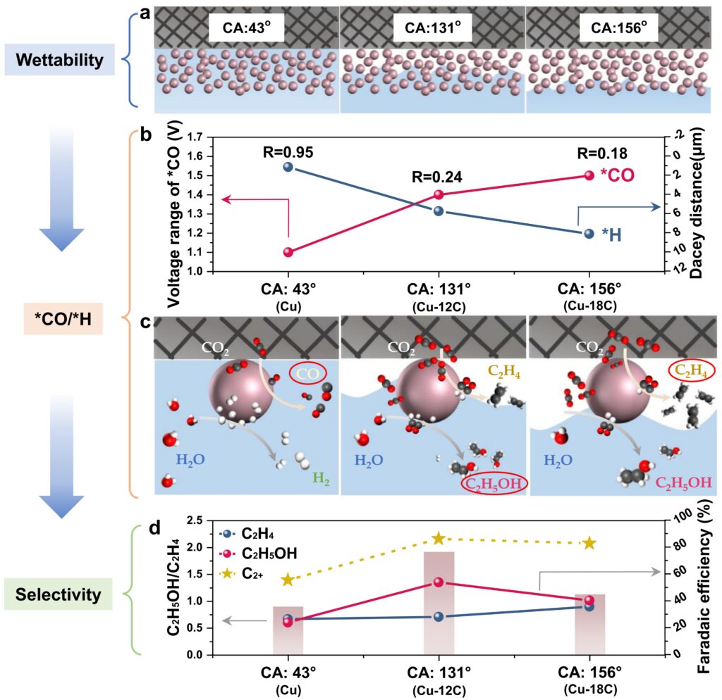
Figure 4. Influence of interfacial wettability on *CO/*H ratio and ethylene/ethanol selectivity. Reproduced from Lin, Y. et al., Nat. Commun. 2023, 14, 3575, Fig. 5, under CC BY 4.0.
6.2 Medium-to-High Current Density Increases the Need for System Control
As reaction rate rises, CO₂ demand, bubble formation, water redistribution, flooding tendency, and salt accumulation become more important. Leonard et al. showed that electrode flooding and gas–liquid-interface management are central to stable gas-fed CO₂ electrolysis [11]. In practice, gas-flow control, electrolyte circulation, EC-WM pressure/water management, and online product analysis should increasingly be treated as controlled experimental variables rather than secondary accessories.
Published examples reinforce this point. Bai et al. reported C₂+ FE remaining above 70.8% after 42 h at 200 mA cm⁻², corresponding to 81.6% retention of the initial C₂+ FE, while Zhou et al. reported stable 14,400 s durability tests at selected potentials [4,8]. Stability data are therefore most meaningful when the complete operating configuration is reported alongside them.
6.3 Reproducibility Starts with Reporting the Complete Configuration
For cross-study comparison and reproducibility, report at least the following:
1. Cell model, anode–cathode gap, and active area.
2. Working-electrode substrate and catalyst loading.
3. Membrane model and pretreatment.
4. Reference and counter electrodes.
5. Electrolyte composition and liquid-flow rate.
6. CO₂ flow rate and gas-side control method.
7. Applied current or potential and the iR-compensation method.
8. Product-analysis method and stability-test duration, when applicable.
Reporting the complete cell, fluid, electrical, and analytical configuration—not only the catalyst and current density—makes it easier to distinguish catalyst-driven changes from system-driven changes and improves comparison across laboratories and publications.
7. Conclusion: From a GDE Cell to a Complete Research Platform
A GDE flow cell should therefore be treated as one part of a coordinated CO₂RR research platform. Reactor geometry, membrane and electrode selection, gas and electrolyte delivery, pressure and water management, electrochemical control, and product analysis collectively define the experimental environment. Published studies using GDE platforms corresponding to the current EC-GDE Series further show that meaningful catalyst performance is inseparable from these operating conditions.
For researchers building or upgrading a CO₂RR platform, the key question is therefore not simply which flow cell to choose, but how the complete experimental system should be configured for the intended reaction, current-density range, stability target, and analytical workflow.
References
[1] Zhang, G.; Zhao, Z.-J.; Cheng, D.; Li, H.; Yu, J.; Wang, Q.; Gao, H.; Guo, J.; Wang, H.; Ozin, G. A.; Wang, T.; Gong, J. Efficient CO₂ Electroreduction on Facet-Selective Copper Films with High Conversion Rate. Nat. Commun. 2021, 12, 5745. https://doi.org/10.1038/s41467-021-26053-w
[2] Lin, Y.; Wang, T.; Zhang, L.; Zhang, G.; Li, L.; Chang, Q.; Pang, Z.; Gao, H.; Huang, K.; Zhang, P.; Zhao, Z.-J.; Pei, C.; Gong, J. Tunable CO₂ Electroreduction to Ethanol and Ethylene with Controllable Interfacial Wettability. Nat. Commun. 2023, 14, 3575. https://doi.org/10.1038/s41467-023-39351-2
[3] Liu, B.; Wang, T.; Wang, S.; Zhang, G.; Zhong, D.; Yuan, T.; Dong, H.; Wu, B.; Gong, J. Back-Illuminated Photoelectrochemical Flow Cell for Efficient CO₂ Reduction. Nat. Commun. 2022, 13, 7111. https://doi.org/10.1038/s41467-022-34926-x
[4] Bai, Y.; Liu, H.; Wang, X.; Xia, T.; Yang, Y.; Chen, J.; Hao, J.; Ning, C.; Shi, W. Efficient CO₂ Electroreduction to Multi-Carbon Products by Nanoconfinement Strategy over Cu Catalyst at Industrial Current Density. Sci. China Mater. 2026, 69, 2747-2756. https://doi.org/10.1007/s40843-025-3818-4
[5] Tao, H.; Wang, F.; Zhang, Z.; Min, S. Surface N-Coordinated Cu Catalysts for CO₂ Electroreduction to Ethylene at Industry-Level Current Densities. Sustain. Energy Fuels 2023, 7, 2991-2996. https://doi.org/10.1039/D3SE00501A
[6] Qing, H.; Cline, E.; Meng, Z.; Li, B.; Li, T.-D.; Mirica, K. A.; Li, W. Protonation Pathway for CO₂ Reduction Mediated by Coordinated H₂O on Active Sites. Nat. Commun. 2025, 16, 11263. https://doi.org/10.1038/s41467-025-66145-5
[7] Chen, X.; Jia, S.; Zhai, J.; Jiao, J.; Dong, M.; Xue, C.; Deng, T.; Cheng, H.; Xia, Z.; Chen, C.; Xing, X.; Zeng, J.; Wu, H.; He, M.; Han, B. Multivalent Cu Sites Synergistically Adjust Carbonaceous Intermediates Adsorption for Electrocatalytic Ethanol Production. Nat. Commun. 2024, 15, 7691. https://doi.org/10.1038/s41467-024-51928-z
[8] Zhou, S.; Wang, J.; Liu, Z.; Gong, T.; Jin, W.; Li, J.; Xu, E.; Wang, M.; Jiang, L. New Insights on In Situ Evolution of Al(OH)₃/CuS Heterostructure towards CO₂ Electrochemical Reduction. Surf. Interfaces 2025, 69, 106779. https://doi.org/10.1016/j.surfin.2025.106779
[9] Burdyny, T.; Smith, W. A. CO₂ Reduction on Gas-Diffusion Electrodes and Why Catalytic Performance Must Be Assessed at Commercially Relevant Conditions. Energy Environ. Sci. 2019, 12, 1442-1453. https://doi.org/10.1039/C8EE03134G
[10] Weng, L.-C.; Bell, A. T.; Weber, A. Z. Modeling Gas-Diffusion Electrodes for CO₂ Reduction. Phys. Chem. Chem. Phys. 2018, 20, 16973-16984. https://doi.org/10.1039/C8CP01319E
[11] Leonard, M. E.; Clarke, L. E.; Forner-Cuenca, A.; Brown, S. M.; Brushett, F. R. Investigating Electrode Flooding in a Flowing Electrolyte, Gas-Fed Carbon Dioxide Electrolyzer. ChemSusChem 2020, 13, 400-411. https://doi.org/10.1002/cssc.201902547
Other Blog Posts You Might Like

For scientists, by scientists.
We give you fast, reliable, and cost-effective access to materials, tools, and equipment, and we…
Read more
Build, Print, Cure: Materials That Make 3D Printing Work
As 3D bioprinting continues to advance rapidly, the performance and functionality of materials have become…
Read more
Knowledge Education: Revving Up for the Singapore Grand Prix: The Science Behind F1 Manufacturing
As the Singapore F1 race approaches, the world’s attention turns once again to this high-speed…
Read more