
CO₂RR Gas Diffusion Electrode Cell Selection Guide
In carbon dioxide reduction reaction (CO₂RR) research, reactor architecture is often as important as the catalyst itself. Many catalysts can show promising preliminary results in an H-type cell (H-cell). However, when the experimental target moves toward medium-to-high current density, long-term stability, or more commercially relevant conditions, conventional H-cells are limited by CO₂ solubility, liquid-phase diffusion pathways, and local pH fluctuations [1,2].
The key advantage of a gas diffusion electrode (GDE) cell is that gaseous CO₂ is delivered from the gas side directly to the vicinity of the catalyst layer, creating a stable gas-liquid-solid three-phase interface. Compared with systems that rely on dissolved CO₂ diffusion, the GDE architecture can markedly shorten the CO₂ mass-transfer pathway and is therefore better suited for CO₂RR catalyst evaluation under medium-to-high current density conditions [1-3]. Figure 1(a) shows the layered architecture of a GDE, including the gas channel, macroporous substrate (MPS), microporous layer (MPL), and catalyst layer (CL). Figure 1(b) further illustrates the internal microstructure of a GDE and the formation of the gas-liquid-solid three-phase interface. Together, these panels explain how the multilayer GDE design shortens the mass-transfer pathway, increases local CO₂ concentration, and maintains the reaction interface required for CO₂RR.
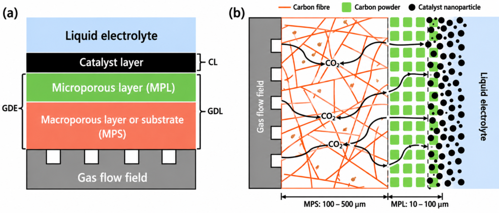
Figure 1. Schematic illustration of (a) the layered GDE architecture and (b) the gas-liquid-solid three-phase interface within the GDE microstructure. Adapted from Hernandez-Aldave and Andreoli [1].
1.Why Are GDE Cells Better Suited for Medium-to-High Current Density CO₂RR?
The mass-transfer limitation in CO₂RR can be understood using a simplified limiting-current expression:
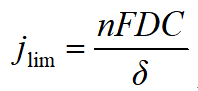
where jlim is the limiting current density, n is the number of transferred electrons, F is the Faraday constant, D is the CO₂ diffusion coefficient, C is the local CO₂ concentration near the catalyst layer, and δ is the effective diffusion-layer thickness. By shortening δ and increasing C near the catalyst layer, GDEs mitigate the CO₂ mass-transfer limitation observed in H-cells [1,2].
In an H-cell, CO₂ first dissolves in the electrolyte and then diffuses to the catalyst surface. This longer mass-transfer pathway makes the local CO₂ concentration prone to solubility limitations, so H-cells are better suited for preliminary screening at low current density. The three-phase interface is less well defined in H-cells, long-term stability is typically poorer, and the hydrogen evolution reaction (HER) can become more pronounced [2].
By contrast, a GDE cell directly delivers gaseous CO₂ to the vicinity of the catalyst layer through the gas diffusion electrode. This substantially shortens the mass-transfer pathway, increases and stabilizes the local CO₂ concentration, and provides a well-defined three-phase interface. GDE cells are therefore suitable for catalyst evaluation and long-term stability testing at medium-to-high current density. Their main challenges include flooding, electrolyte salt precipitation, pressure-difference control, and sealing reliability, but they provide an experimental environment closer to continuous-flow reactors and can therefore reflect catalyst performance more realistically [1-3].
2. Core Selection Dimensions: Match the Experimental Stage, Not Simply the Shortest Gap
When selecting a GDE cell, five dimensions should be considered: experimental objective, materials and sealing, electrode area and gap, flow field and gas path, and electrochemical configuration.
Table 1. Five Key Dimensions for GDE Cell Selection
|
Dimension |
Key Questions (Including Technical Considerations) |
Impact on Selection |
|
Experimental Objective |
Entry-level or preliminary screening vs. medium-to-high current density vs. long-term diagnostics?
|
This dimension defines the reactor design logic. Preliminary screening focuses on rapid catalyst activity validation; standard evaluation emphasizes three-phase-interface stability and accurate product analysis; mechanistic studies often require observation windows and flexible reference-electrode placement; medium-to-high current density and long-term stability tests require low ohmic loss, resistance to flooding, and long-term sealing reliability [1-3]. |
|
Cell Body Material |
PMMA, PTFE, PEEK, or Ti?
|
This dimension determines long-term structural stability. Materials affect not only chemical resistance but also retention of compression force, membrane compression uniformity, contact resistance stability, and sealing lifetime [3,6]. |
|
Electrode Area and Gap |
1 cm² or a larger active area? How short should the gap be?
|
This dimension determines ohmic loss and scale-up feasibility. Shortening the gap can reduce ionic transport resistance and cell voltage, but it also increases the risk of flooding, salt precipitation, and sealing failure [4,6]. |
|
Flow Field and Gas Path |
Straight-through, parallel, serpentine, or custom flow field?
|
This dimension determines mass-transfer efficiency and water-management capability. The flow field affects not only CO₂ delivery but also liquid removal, bubble detachment, pressure distribution, and product removal [1,6]. |
|
Electrochemical Configuration |
Are the reference-electrode position, membrane type, and electrochemical impedance spectroscopy (EIS) setup appropriate?
|
This dimension determines data reliability and inter-laboratory comparability. The RE position affects whether the measured potential reflects the working-electrode potential; membrane type affects ion transport, local pH, and product crossover [3,4,7]. |
The cell voltage can be decomposed as:
Ecell = Ethermo + ηcathode + ηanode + iRΩ + ηtransport
where Ecell is the actual cell voltage, Ethermo is the thermodynamic equilibrium potential, ηcathode and ηanode are the cathodic and anodic overpotentials, respectively, iRΩ is the ohmic loss, and ηtransport is the mass-transport overpotential. In a GDE flow cell, a short-gap design primarily affects the iRΩ term, but bubbles, salt precipitation, and membrane resistance can also change the actual cell voltage [4,6,7].
The ohmic term (iRΩ) is related to the electrode gap, electrolyte conductivity, membrane resistance, contact resistance, and local resistance caused by bubbles or salt precipitation. In principle, a shorter electrode gap shortens the ionic transport pathway and reduces ohmic loss:
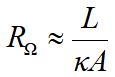
where L is the cathode-anode distance, κ is the electrolyte conductivity, and A is the effective reaction area. With the same electrolyte and effective area, reducing L can lower RΩ. However, when L becomes too short, sealing, membrane compression, assembly torque, flow-field liquid removal, and gas-liquid pressure balance become new limiting factors.
Therefore, GDE cell selection should not simply pursue the shortest possible gap. It should be based on the target current density, stability-test duration, need for observation windows, and reference-electrode placement.
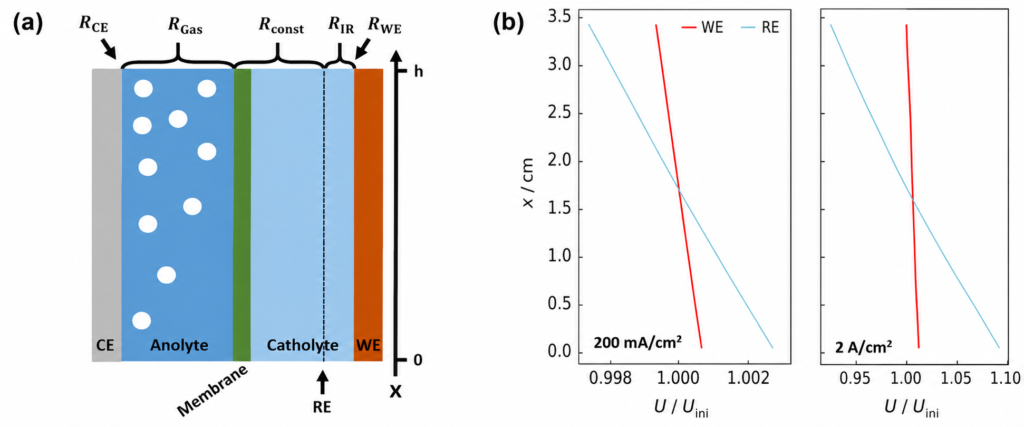
Figure 2. Illustration of (a) gas-evolution-induced resistance gradients and (b) the resulting reference-electrode measurement error. Adapted from Jännsch et al. [6].
As shown in Figure 2(a), the large amount of gas generated during medium-to-high current density operation can create a pronounced resistance gradient along the flow direction, thereby increasing ohmic loss. As further shown in Figure 2(b), this non-uniform spatial resistance distribution causes reference electrodes placed at different positions to measure different working-electrode potentials, leading to systematic bias in the experimental results. Therefore, in GDE flow-cell testing, researchers should pay attention not only to catalyst performance but also to bubble management, flow-field design, and reference-electrode placement to ensure data accuracy and comparability [6].
3. Key Challenges in Long-Term GDE Operation
The real difficulty in GDE testing is not merely whether the system can run, but whether it can operate stably, reproducibly, and interpretably. In long-term CO₂RR experiments, the most common issues include flooding, salt precipitation, membrane dry-out, gas leakage, bubble accumulation, and reference-potential error [3-8].
Table 2. Common Failure Modes and Mitigation Strategies in GDE-Based CO₂RR Systems
|
Failure Mode |
Underlying Mechanism |
Impact on CO₂RR Performance |
Mitigation Strategies |
|
Flooding |
Electrolyte penetrates GDL/MPL pores and blocks gas-transport pathways. |
Restricted CO₂ transport, increased HER, and lower CO₂RR selectivity. |
Maintain gas-liquid pressure balance, preserve GDE hydrophobicity, and optimize flow rates. |
|
Salt Precipitation |
Carbonate/bicarbonate deposits form from reactions between CO₂, OH⁻, and alkali-metal cations. |
Pore blockage, reduced CO₂ accessibility, and long-term stability decay. |
Optimize electrolyte composition and water management; apply periodic flushing when necessary. |
|
Gas Leakage |
Insufficient sealing or uneven compression. |
Distorted product quantification and inaccurate carbon balance. |
Verify sealing integrity and fitting connections before operation. |
|
Bubble Accumulation |
Incomplete removal of gaseous products during electrolysis. |
Increased iR loss, current fluctuations, and potential drift. |
Improve electrolyte circulation and optimize flow-field design. |
|
Membrane Dry-Out |
Insufficient water transport or dry gas feed. |
Reduced ionic conductivity and increased cell voltage. |
Maintain adequate humidification and optimize water management. |
|
Membrane Crossover |
Limited membrane selectivity or membrane degradation. |
Product crossover and biased FE measurements. |
Select appropriate membrane types and replace aged membranes when necessary. |
|
Catalyst-Layer Delamination |
Mechanical stress or insufficient adhesion within the catalyst layer. |
Activity decay and poor reproducibility. |
Optimize catalyst-layer fabrication and assembly conditions. |
|
High Contact Resistance |
Poor electrical contact between cell components. |
Increased energy loss and inaccurate efficiency evaluation. |
Improve compression uniformity and electrical contact. |
|
Reference-Potential Error |
Resistance gradients and inappropriate reference-electrode placement. |
Non-comparable electrochemical data. |
Position the reference electrode close to the working electrode and report Ru with the iR-compensation method. |
Flooding is one of the most typical failure modes in GDE systems. When electrolyte enters the pores of the gas diffusion layer (GDL) or microporous layer (MPL), gas channels originally used for CO₂ transport become occupied by liquid. This restricts CO₂ diffusion, enhances local HER, and decreases the FE of target products. The quartz-window designs of EC-GDE3 and EC-GDE4 help researchers observe interfacial states and are especially useful for diagnosing flooding and bubble retention [1,3,6].
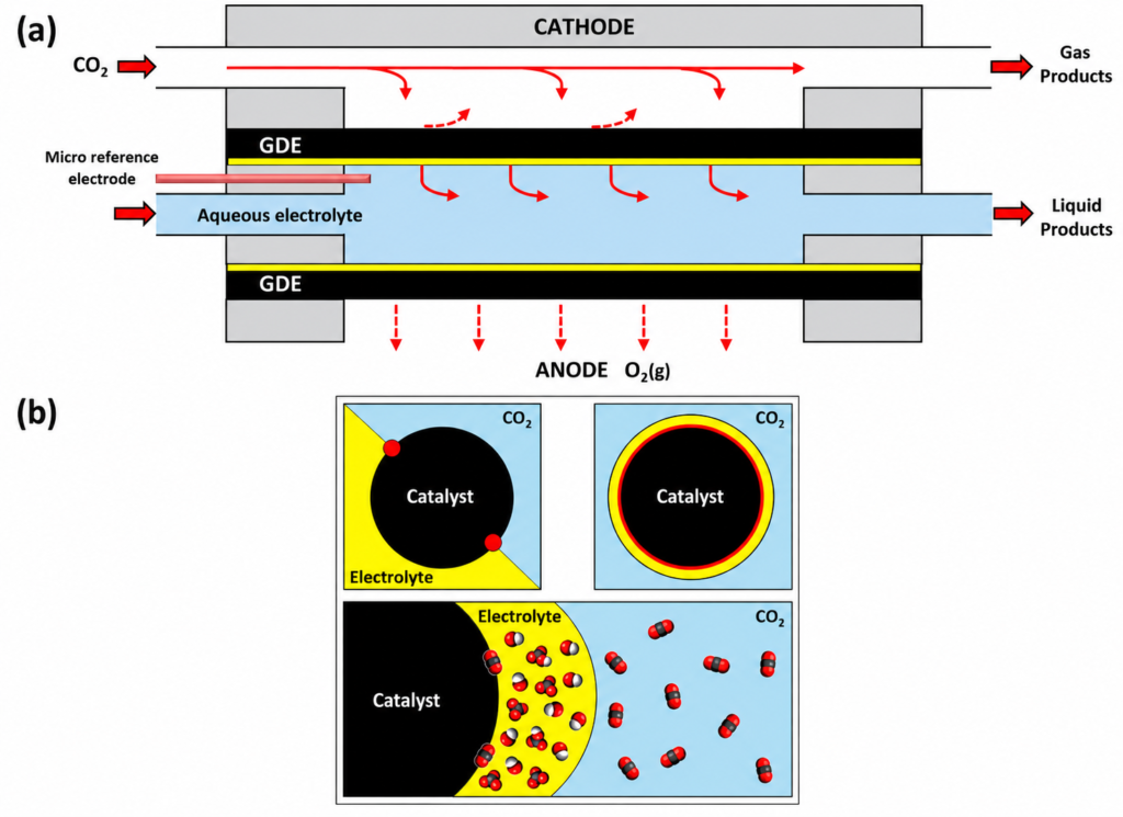
Figure 3. Illustration of (a) the GDE flow-cell architecture and (b) the impact of flooding on the gas-liquid-solid three-phase interface. Adapted from Hernandez-Aldave and Andreoli [1].
As shown in Figure 3(a), the GDE flow cell delivers gaseous CO₂ directly to the vicinity of the catalyst layer, forming a gas-liquid-solid three-phase interface on the catalyst surface. This shortens the CO₂ mass-transfer pathway and increases the local reactant concentration. At the same time, maintaining the stability of this three-phase interface is critical for medium-to-high current density operation. As shown in Figure 3(b), when electrolyte gradually penetrates GDL and MPL pores, the gas-transport channels are occupied by liquid, resulting in flooding. Flooding not only reduces CO₂ transport to the catalyst layer but also causes local CO₂ depletion and OH⁻ accumulation, thereby enhancing HER and lowering the selectivity toward CO₂ reduction products [1,3,6].
Salt precipitation is another key issue during medium-to-high current density and long-term operation. OH⁻ generated locally at the cathode reacts with CO₂ to form HCO₃⁻ and CO₃²⁻, which can then combine with K⁺ or Na⁺ to form carbonate/bicarbonate deposits. Salt precipitation may occur in GDE pores, gas channels, near the membrane, or in the catalyst layer, ultimately blocking CO₂ pathways and increasing gas pressure drop [4,7,8].
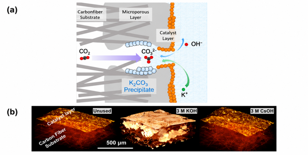
Figure 4. Illustration of (a) carbonate/bicarbonate formation and deposition in GDEs and (b) microscopic evidence of salt deposits on GDE surfaces. Adapted from Chen, Wu and Qian [7] and Cofell et al. [8].
Figure 4(a) illustrates the deposit-formation mechanism, while Figure 4(b) provides experimental microscopic evidence of salt accumulation on GDE surfaces. Together, these results highlight that long-term GDE stability depends not only on catalyst activity but also on effective management of gas transport, water balance, and electrolyte chemistry.
CO₂ + OH⁻ ⇌ HCO₃⁻
HCO₃⁻ + OH⁻ ⇌ CO₃²⁻ + H₂O
K+/Na+ + CO₃²⁻/HCO₃⁻ → K₂CO₃/Na₂CO₃/KHCO₃/NaHCO₃ (s)
Therefore, selection of a GDE cell should not focus only on electrode gap. Flow-field liquid-removal capability, sealing reliability, gas-liquid pressure balance, and ease of maintenance must also be considered [4,5,7,8].
4. Recommended GDE Cell Models
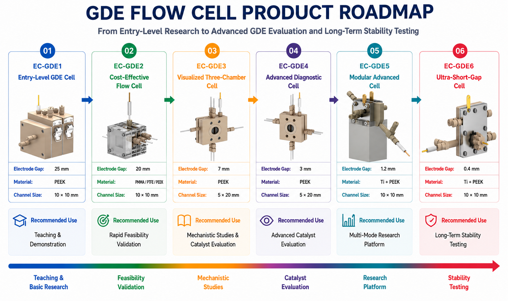
Figure 5. Product roadmap for CO₂RR GDE cells, covering entry-level testing, standard catalyst evaluation, visual diagnostics, short-gap operation, and MEA-type stability testing.
5.Quick Selection Recommendations
If you are new to GDE systems, choose EC-GDE1 first. It is suitable for becoming familiar with GDE assembly, gas inlet/outlet handling, electrolyte circulation, and basic three-electrode testing.
If you want to build a low-cost flow-cell testing workflow, choose EC-GDE2. This series is suitable for rapidly validating gas-diffusion systems, but the 20 mm gap means that iR compensation deserves closer attention under medium-to-high current density operation.
If your experiments often show current fluctuations, FE drift, or suspected GDE flooding, choose EC-GDE3 or EC-GDE4. The quartz window can significantly improve diagnostic capability.
If you want to move into short-gap, medium-to-high current density, or more complex reactor studies, choose EC-GDE5.
If your target is medium-to-high current density, long-term stability, or MEA-oriented testing, choose EC-GDE6. Its 0.4 mm short gap and serpentine flow field are better suited for stable operation under medium-to-high current density.
6.Conclusion
GDE cell selection for CO₂RR is fundamentally a balance among mass transfer, ohmic loss, three-phase-interface stability, and long-term operational reliability. For principal investigators, postdoctoral researchers, and research engineers, a rational upgrade path is not to select the most advanced model immediately, but to proceed step by step according to the experimental stage: first establish a stable GDE three-phase interface, then optimize iR drop and flow-field design, and finally move toward short-gap, MEA, and long-term stability testing.
Models EC-GDE1-EC-GDE6 are not merely a list of products. They form a GDE cell product matrix covering entry-level use, standard evaluation, visual diagnostics, advanced short-gap testing, and MEA-type medium-to-high current density testing.
7.FAQ
Q1: Why does CO₂RR require a GDE cell?
Because H-cells are limited by CO₂ solubility and liquid-phase diffusion, making it difficult to sustain medium-to-high current density. A GDE enables gaseous CO₂ to reach the vicinity of the catalyst layer directly, improving CO₂ accessibility.
Q2: Is a shorter electrode gap always better?
Not necessarily. A short gap can reduce ohmic loss, but it also imposes higher requirements on sealing, compression, membrane positioning, gas-liquid pressure balance, and assembly consistency.
Q3: Why does GDE flooding occur?
It mainly occurs when electrolyte enters GDL/MPL pores and blocks CO₂ transport pathways. Possible causes include pressure imbalance, loss of hydrophobicity, sealing issues, and wetting-state changes during long-term operation.
8. References
[1] Hernandez-Aldave, S.; Andreoli, E. Fundamentals of Gas Diffusion Electrodes and Electrolysers for Carbon Dioxide Utilisation. Catalysts 2020, 10, 713. https://doi.org/10.3390/catal10060713
[2] Burdyny, T.; Smith, W. A. CO₂ Reduction on Gas-Diffusion Electrodes and Why Catalytic Performance Must Be Assessed at Commercially Relevant Conditions. Energy Environ. Sci. 2019, 12, 1442–1453. https://doi.org/10.1039/C8EE03134G
[3] Lees, E. W.; Mowbray, B. A. W.; Parlane, F. G. L.; Berlinguette, C. P. Gas Diffusion Electrodes and Membranes for CO₂ Reduction Electrolysers. Nat. Rev. Mater. 2022, 7, 55–64. https://doi.org/10.1038/s41578-021-00356-2
[4] Sassenburg, M.; Suermann, M.; Tisserant, J.-N.; Sinev, I.; Billard, A.; Roldan Cuenya, B.; Cherevko, S. Zero-Gap Electrochemical CO₂ Reduction Cells: Challenges and Operational Strategies for Prevention of Salt Precipitation. ACS Energy Lett. 2023, 8, 321–331. https://doi.org/10.1021/acsenergylett.2c01885
[5] Wakerley, D.; Lamaison, S.; Ozanam, F.; Menguy, N.; Mercier, D.; Marcus, P.; Fontecave, M.; Mougel, V. Gas Diffusion Electrodes, Reactor Designs and Key Metrics of Low-Temperature CO₂ Electrolysers. Nat. Energy 2022, 7, 130–143. https://doi.org/10.1038/s41560-021-00973-9
[6] Jännsch, Y.; Voß, D.; Bungert, L.; Baltruschat, H. Gas Evolution in Electrochemical Flow Cell Reactors Induces Resistance Gradients with Consequences for the Positioning of the Reference Electrode. RSC Adv. 2021, 11, 28189–28197. https://doi.org/10.1039/D1RA05345K
[7] Chen, Y.; Wu, B.; Qian, L. Proton Pool for the Mitigation of Salt Precipitate Enhancing CO₂ Electroreduction in a Flow Cell. Catalysts 2024, 14, 807. https://doi.org/10.3390/catal14110807
[8] Cofell, E. R.; Kuhl, K. P.; Hatsukade, T.; Cave, E. R.; Abram, D. N.; Jaramillo, T. F. Investigation of Electrolyte-Dependent Carbonate Formation on Gas Diffusion Electrodes for CO2 Electrolysis. ACS Appl. Mater. Interfaces 2021, 13, 15132–15142. https://doi.org/10.1021/acsami.0c21997
Other Blog Posts You Might Like

Understanding Electrolytic Cells: Types, Components, and Applications
An electrolytic cell is an essential electrochemical device that drives a non-spontaneous redox reaction using…
Read more
Building a Reliable CO₂RR Experimental Platform: System Design, Fluid Management, and Mass Transport Optimization
Introduction with the rapid development of CO2 electroreduction research, an increasing number of laboratories are…
Read more
Knowledge Education: Choosing the Right Reference Electrodes for Your Research
A reference electrode is used as a benchmark to measure the potential difference relative to…
Read more